
This is a detailed step-by-step on how to set up addressable RGB LED stripes in your virtual pinball machine using a Teensy 3.2 controller board.
Three effects make a virtual pinball feel realistic: Haptics, like noticeable feedback while playing, atmospheric sound and: stunning lighting effects.
Setting up LED stripes in my cabinet took me many hours, so I decided to put together this “tutorial” to help any fellow builders in their quest. Let me know if it is helpful 😉
I have installed two types of additional lighting effects: 5 LED flasher (more on this later) and colored RGB LED RGB stripes. These are attached to the left and right of the Playfield monitor and additionally at the bottom of the cabinet and the back of the cabinet backbox.
The effect is similar to the “ambient” effect that many large-format televisions have and which gives the image a spatial depth.
Test of the setup of the addressable RGB LED stripes with colour gradients.
How to setup addressable RGB LED stripes in a virtual pinball cabinet
RGB LED Stripes: this is the hardware you need
Basically you need RGB LED Stripes and some piece of hardware to address the LEDs on the stripes via DOF (Direct Output Framework) for each table.
In my VPin, the following setup works nicely:
- RGB LED Stripes WS2812B Led stripes, 60 Leds/m Type 5050 RGB SMD (Source: Amazon.com). LED strips are available from a huge variety of vendors and come in different LED densities starting from 30 LEDs/m up to 144 LEDs/m (WS2811/WS2812). The price goes up fast as you reach higher density LED strips. If you are planning a matrix for the back of the cabinet density will determine resolution so I guess more LEDs is better. For my application I am making flashing, pulsing, strobing light effects for the side of the cab so I went with 60 LED/m stripes. Make sure you don’t fall like me for cheap Chinese stripes first, which obviously don’t match the WS2812B norm and cause a lot of frustration. If you want a recommendation: WS2812B 300 Pixels 5050 SMD for about 36 Euro / 5m Stripe. Source: Amazon.com
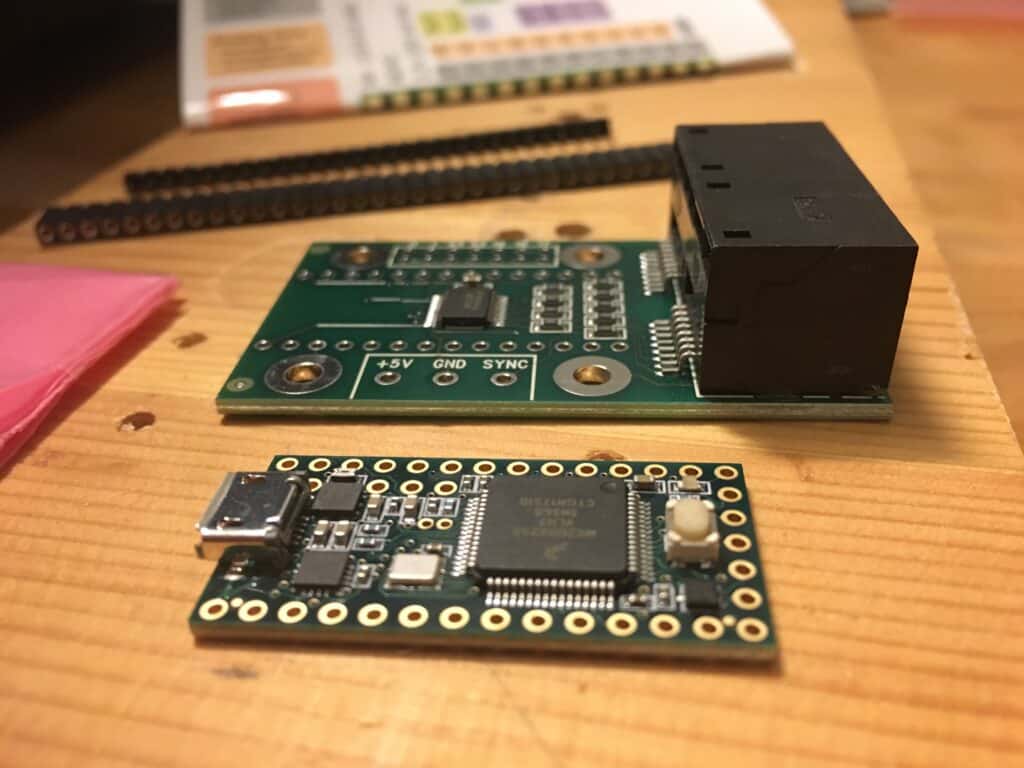
- Development board Teensy 3.2 USB for controlling the LEDs via USB (Source: Amazon.com). I can’t tell it there is any benefit of newer generations of the board – the step-by-step refers to 3.2. The board is available with or without pins. You will need the pins to connect it to the adapter card. So it is up to you, if you like soldering like I do.
- Teensy Octo WS2811 adapter card for connecting two RJ45 network plugs. The individual LED stripes are connected to the insulated veins of the network plugs. (Source: Amazon.com).
“The Teensy is a complete USB-based microcontroller development system that can realize many types of projects on a very small basis. All programming is done via the USB port. No special programmer is needed, just a standard micro-B USB cable and a computer with a USB port. ” (Amazon.com)
Too late for my setup I realized that Dominik Dancsó of German Gaming Supplies provides a neat Teensy Control Box that helps with the cable management.

Video Tutorial setting up RGB LED stripes with Teensy 3.2
If you don’t like to read, I would like to recommend the following youtube video tutorial from “Game Room Solutions” which covers connecting the LEDs, setup of the Teensy and DOF configuration. Simply follow it 1:1, then it should work right away.
Nevertheless I will give you a step-by-step of how to set up addressable RGB LED stripes for your virtual pinball machine:
1. Wiring of LED stripes to Teensy
The first step is to connect your LED stripes to the Teensy board.
Have a look at your LED stripes: The LED strips are one-directional in their signal flow and there is (should be) a marker with arrows to show that direction. Power and ground can be injected from any location in the strip but the signal has to come come from the starting end.
As these LEDs are rather power hungry, for very long lengths or dense matrixes power needs to be injected every 180 LEDs per one source. Of course you can make longer chains as far as data is concerned, but power has to be injected at least every 180 LEDs. Usually these LED strips run on 5V.
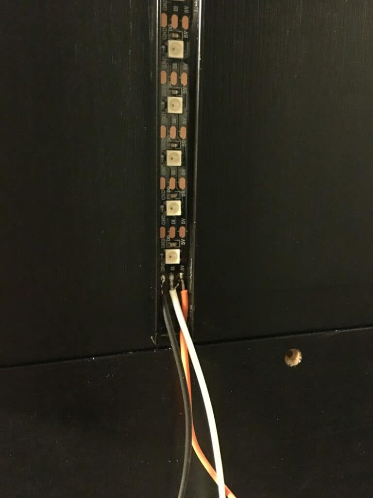
The LED strips need +5v and ground to the outer two pads (black and red).
If you are using the Octo28 adaptor you can connect a CAT6 cable plug to one of the two RJ45 sockets. The CAT6 cable has 4 twisted wires, giving you signals to 4 different stripes. As there are 2 sockets, using one Octo28 adaptor allows you to address up to 8 separate LED stripes. Which is a lot of fun.
The order of twisted pairs of the CAT6 cable is:
Orange
Blue
Green
Brown
With the solid color being the data wire and the white being the ground.
The jack on the right (holding the jacks towards you) sends signals 1-4 and the jack on the left signals 5-8.
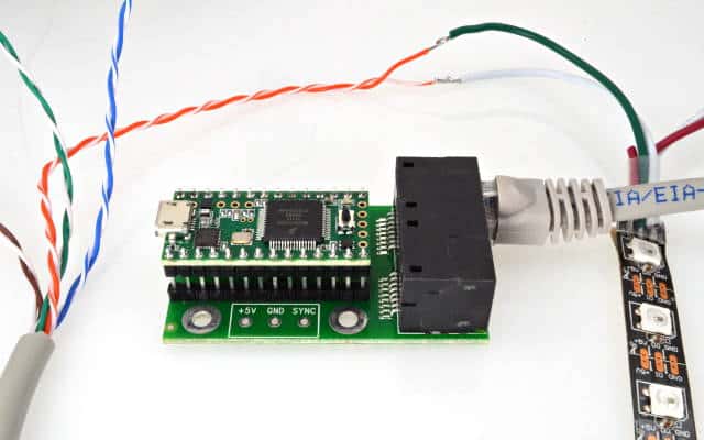
Most LED strips use black as ground (GND) and white as data so you need to hook up the colored CAT6 wire to white on the LED strip and the white CAT6 wire to the black (GRN) on the LED strip.
Teensy sees – as far a I can tell – the LED strips as one long continuous strip. This does not mean that you have to daisy chain the strips by sending the signal out at the end of one strip and into the beginning of another but can address them separately.
If you’ve decided where to place the stripes in you cabinet, measure and cut the long stripe in the appropriate pieces. Make sure you cut the soldering spots in half so there is enough ground for a good connection.
For the following Teensy setup you should have a test-stripe of about 50cm length (just to see effects, any length will do).
2. Setting up Teensy for LED stripes
The Teensy board connects up to your PC via USB cable so you need a cable with a regular USB on one end and a micro USB on the other (Source: Amazon.com).
The Teensy now needs to be loaded with software to run the LED strips. The instructions for doing this are available here:https://github.com/DirectOutput/TeensyStripController
As I did not get along with this, I recommend watching this part of the video tutorial and following it step by step:
Part 2: Software, firmware and Teensy test
https://www.youtube.com/watch?v=KfSCzqKx1G
Hopefully you have your LEDs glowing in beautiful colors at this point. If not, check your wiring and watch the video tutorials one more time.
3. How to Setup Teensy and DOF in a virtual pinball
The last part is about how to get the Direct-Output-Framework (DOF) of your virtual pinball machine to talk to the Teensy controller. For this, you need a Global Configuration file and a Cabinet Configuration file in your Directoutput/Config folder.
This is a copy of my Global Configuration file:
<?xml version="1.0" encoding="utf-8"?>
<!--Global configuration for the DirectOutput framework.-->
<!--Saved by DirectOutput Version 0.8.6002.28451: 2019-04-26 22-43-10-->
<GlobalConfig>  <LedWizDefaultMinCommandIntervalMs>1</LedWizDefaultMinCommandIntervalMs>  <LedControlMinimumEffectDurationMs>60</LedControlMinimumEffectDurationMs>  <LedControlMinimumRGBEffectDurationMs>120</LedControlMinimumRGBEffectDurationMs>
<IniFilesPath />
<ShapeDefintionFilePattern>{DllDir}\DirectOutputShapes.xml</ShapeDefintionFilePattern>  <CabinetConfigFilePattern>C:\DirectOutput\config\CabinetConfig.xml</CabinetConfigFilePattern>
<TableConfigFilePatterns />  <EnableLogging>true</EnableLogging>  <ClearLogOnSessionStart>false</ClearLogOnSessionStart>  <LogFilePattern>.\DirectOutput.log</LogFilePattern>
</GlobalConfig>
And this is a copy of my Cabinet configuration file. As there is not a lot of information available on how to set it up, it is a little tricky. To make it easy for you, I’ll add comments in bold to explain what is going on. Make sure you do not copy these comments in your XML. Otherwise you will have errors.
<?xml version="1.0" encoding="utf-8"?>
<!-- This config file will set up two addressable LED strips orange on the right and blue on the left. Each is 53 long and have the distal LED as the first in the array -->
<Cabinet xmlns:xsi="http://www.w3.org/20...chema-instance" xmlns:xsd="http://www.w3.org/2001/XMLSchema">
<Name>Virtual Pinball</Name> Name of cabinet
<OutputControllers>
<TeensyStripController>
<Name>TeensyStripController</Name>      <NumberOfLedsStrip1>53</NumberOfLedsStrip1>  Number of LEDs right playfield
<NumberOfLedsStrip2>53</NumberOfLedsStrip2>  Number of LEDs left playfield
<NumberOfLedsStrip3>0</NumberOfLedsStrip3>      <NumberOfLedsStrip4>0</NumberOfLedsStrip4>      <NumberOfLedsStrip5>0</NumberOfLedsStrip5>      <NumberOfLedsStrip6>0</NumberOfLedsStrip6>      <NumberOfLedsStrip7>0</NumberOfLedsStrip7>      <NumberOfLedsStrip8>0</NumberOfLedsStrip8>      <ComPortName>COM3</ComPortName> Check in device manager to find out what port Windows assigned for the Teensy USB connection on your machine!!    </TeensyStripController>
</OutputControllers>
<Toys>
<LedStrip>
<Name>PF Right</Name> My name for the the right playfield strip      <Width>1</Width> These strips runs as one long string as far as the Teensy board is concerned. Dont't change
<Height>53</Height> Length of the right playfield LED array      <LedStripArrangement>TopDownLeftRight</LedStripArrangement> There are several choices that can be used here like BottomUpLeftRight.  This determines the order of LEDs that the Teensy sends out on its signal path. If you use TopDown then the furthest LED from the connecting wires will be the first one in the segnal pathway.      <ColorOrder>GRB</ColorOrder> You must choose GRB not RBG with these strips to get them to correctly display the colors sent to them      <FirstLedNumber>1</FirstLedNumber> This is the first strip so it starts with LED 1      <FadingCurveName>SwissLizardsLedCurve</FadingCurveName> Honestly can't tell you what this does. Just leave it like is. <OutputControllerName>TeensyStripController</OutputControllerName>    </LedStrip>
<LedStrip>
<Name>PF Left</Name> Same a above
<Width>1</Width>
<Height>53</Height>      <LedStripArrangement>TopDownLeftRight</LedStripArrangement>      <ColorOrder>GRB</ColorOrder>      <FirstLedNumber>54</FirstLedNumber> Since this is the second strip its first LED is the next one after the last LED on the other strip so since my strips are 53 LEDs long it is LED 54.      <FadingCurveName>SwissLizardsLedCurve</FadingCurveName>
<OutputControllerName>TeensyStripController</OutputControllerName>    </LedStrip>
<LedWizEquivalent>
<Name>LedWizEquivalent 30</Name> Number assigned to the WS2811 controller by the online DOF config tool
<Outputs>
<LedWizEquivalentOutput><OutputName>PF Right</OutputName> Name as above          <LedWizEquivalentOutputNumber>1</LedWizEquivalentOutputNumber> This is the port number of the first set of combos set up In the online DOF Config tool so it is port 1
</LedWizEquivalentOutput><LedWizEquivalentOutput>          <OutputName>PF Left</OutputName> Name as above          <LedWizEquivalentOutputNumber>4</LedWizEquivalentOutputNumber> This is the port number of the second set of combos set up in the online DOF config tool so it is port 4 </LedWizEquivalentOutput>      </Outputs>
<LedWizNumber>30</LedWizNumber>
</LedWizEquivalent>
</Toys> <AutoConfigEnabled>true</AutoConfigEnabled> This needs to be set to true to work
</Cabinet>
4. Last Step: Create new config-file in DOF config-tool.
You are almost there: Now open the DOF online config tool, sign in and create a new config file that includes a WS2811 controller:
- Go to the My Account tab and increase the number of WS2811 Devices to 1 (for the Teensy board).
- Go to Combine Toys and make two combos one for the right PF Flashers MX and PF Effects MX and one for the left.
- Finally go to the Port Assignments Tab, choose the WS2811 – directoutputconfigini30 device and assign port 1 to your first LED strip (1 red, 2 green, 3 blue) and port 4 for the second LED strip (4 red, 5 green, 6 blue).
- In Port Assignments Tab click “Generate Config”, download the ZIP and extract the files into your Directoutput/Config folder. Make sure they are not blocked (Windows).
This is about it.
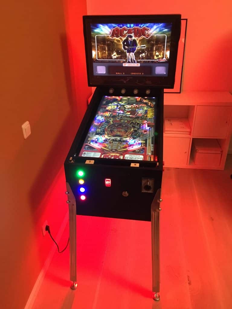
When the LED finally were running, watching the new effects on each table was a big surprise: From simple color flashing effects depending on the game situation, to running lights tracking the ball in the shooter lane to stunning lightning effects, as soon as certain targets on the playing field were hit.
In any case, the effort is worth it. In particular, the LED strips to the left and right of the playfield monitor now add visual depth to the table.
How to mount RGB LED Stripes on your virtual pinball
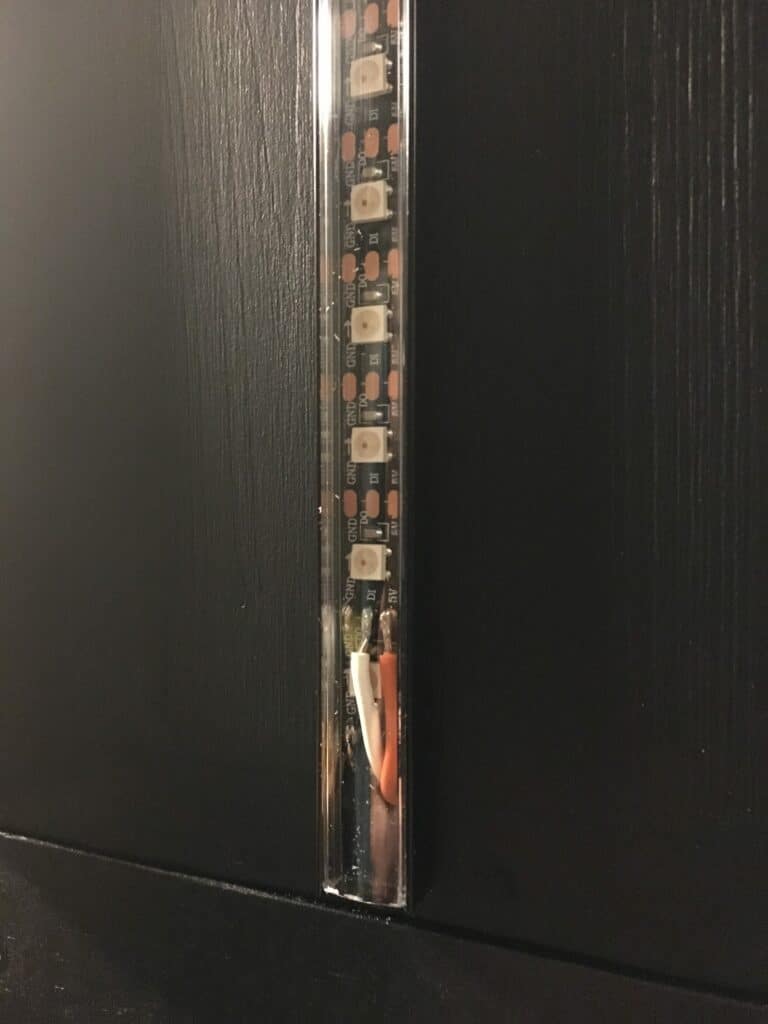
The following photo shows the LED strip on the backside of the cabinet backbox. The black aluminium profile was screwed onto the backbox, then a thin, double-sided foam tape was glued into the profile as insulation. The RGB LED stripe has a double sided tape on the backside and is covered by the transparent cover of the profile.
The fully assembled LED strip under the transparent protective cover of the aluminium profile:
Parts-List for Virtual Pinball
In the parts section I’ve made a list of (most) of the parts I’ve installed in my virtual pinball and where I’ve bought them: Virtual Pinball machine parts list.
Next:
How to install an analog plunger in a virtual pinball machine…


Comments (6)
Josh Francissays:
30/05/2020 at 05:47Your tutorials flat out ROCK! Thank You. I’m a newby and an idiot with this type of stuff yet you make it soooo easy to follow. Thanks so much!
vpintill74says:
30/05/2020 at 07:09Thanks Josh! Glad it helps 🙂 Have fun!
Alsays:
18/02/2020 at 17:41Great tutorial! I was able to follow along most of it, but where I’m a little confused is where do you set it up in VPX to talk to DOF? I have FP and FX3 all working great with this setup but VPX doesn’t seem to use the LEDs at all, which is weird and leads me to think I’m missing something in the setup process.
Thanks!
vpintill74says:
22/02/2020 at 20:32Hi AI, thanks for your post.
You have to set up the Teensy in DOF-Config tool: http://configtool.vpuniverse.com/login.php.
I’ve added a new Video from “Mame in a Box” in the posting, this will be helpfull: https://www.virtual-pinball-cabinet.com/set-up-addressable-led-strips-virtual-pinball/
Hope this helps!
Till
Teil 9: Setup Addressable LED Stripes im Virtual Pinball - virtual-pinball-cabinet.comsays:
04/05/2019 at 19:40[…] eine ausführliche Step-By-Step Anleitung zur Installation von RGB LEDs in einem Virtuellen Pinball habe ich in der englischen Version dieses Blogs […]
Part 2: Building a Virtual Pinball Backbox - virtual-pinball-cabinet.comsays:
29/04/2019 at 20:21[…] For additional visual effects, if’ve mounted two rows of addressable RGB LED stripes on the backside of the pinball cabinet backbox. Here’s a step-by-step on how to set up LEDs stripes in your virtual pinball using a Teensy controller board. […]