With most of the the woodwork done and pinball cabinet and pinball backbox are assembled, the next step is to install and wire the pinball buttons. My goal was to be able to control the pinball software completely without a keyboard or mouse and to achieve the most realistic experience when playing through the use of real pinball buttons and switches.
Usually, pinball software such as Visual Pinball or Future Pinball is played via a keyboard. In a virtual pinball machine, the mechanical pinball buttons and switches are wired to a “keyboard emulator,” which then simulates the keystroke as if pressed on a keyboard and returns the signal it to the pinball software.
Virtual Pinball Controller
There are a lot of pinball controllers available on the market. To name just a view:
- Pincontrol 1 – nice board with integrated input and outputs for DOF, nudging and analog plunger support.
- Pincontrol 2– updated version with 24 input ports and 48 outputs for large projects.
- PinIn 1 – supports only input (like buttons) but also nudging and anlog plunger. This is my choice.
- LEDWiz – only outputs (like RGB LEDs, Toys etc.). Works nice with the PinIn 1.
- Pinscape – popular DIY board with nudging using the kl25z.
- Teensy and OctoWS2811 Adaptor for addressable LEDs. I use this combo to run my LED stripes via DOF. Nice.
Please see the virtual pinball machine components & parts-list for shops where to get the boards.

In my Virtual Pinball, a PinIn1 board (center) is used. The board (input only) is already a little older and does not support RGB LED buttons, but in addition to the keyboard encoder, it has a motion sensor that makes it easy to simulate a realistic tilt mechanism (nudging): Pushing against the table makes the ball deviate – or TILT!
Which Buttons to you need in a Virtual Pinball Machine?
I use the following setup in my cabinet:
- 2 Leaf Switch pinball buttons left (Flipper-Finger button, Magna Save button)
- 2 Leaf Switch pinball buttons on the right
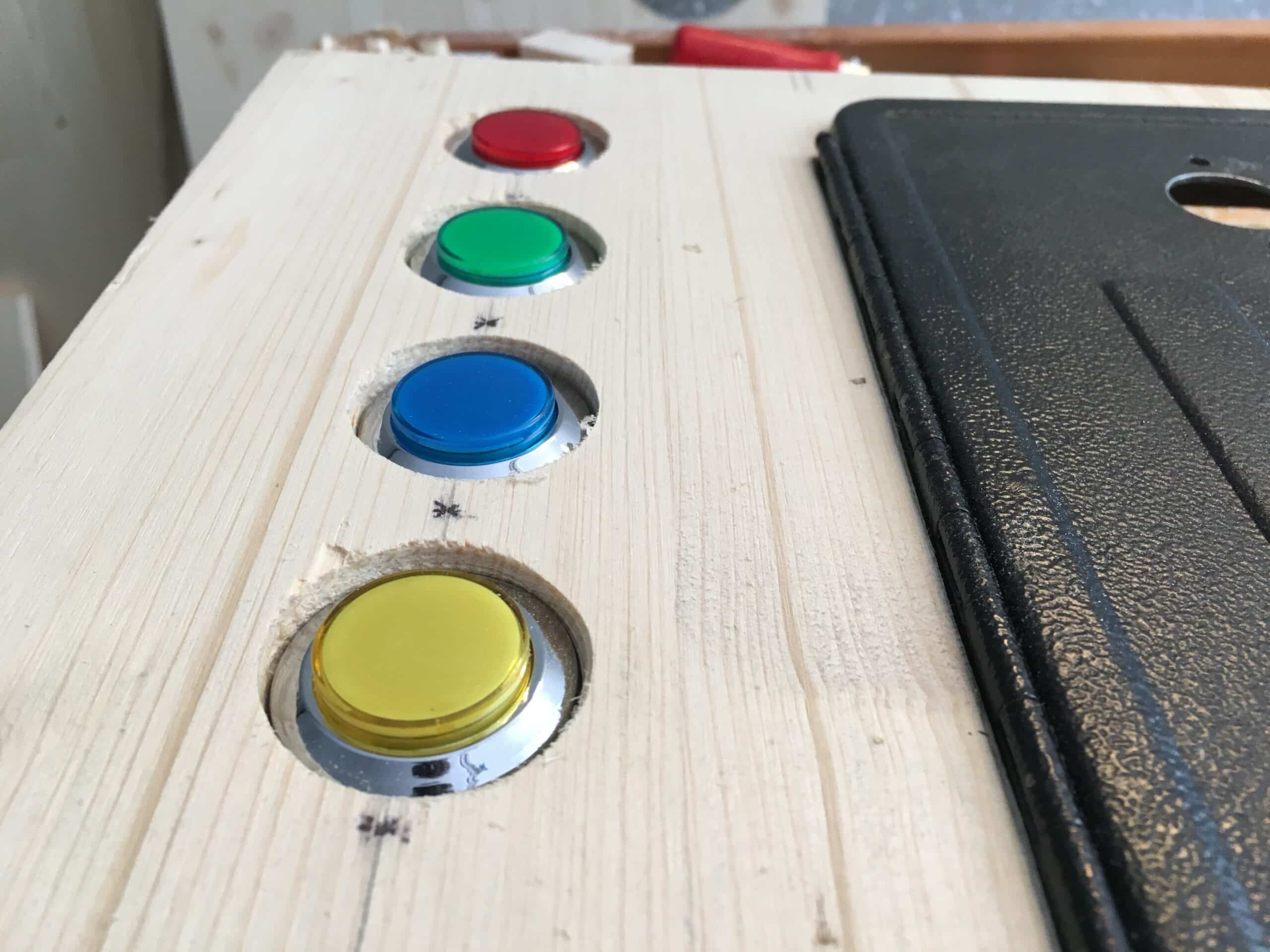
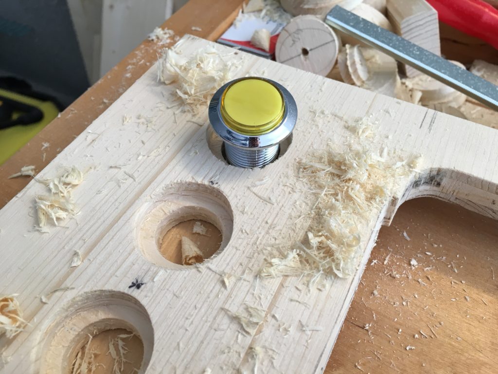
- 4 colored LED arcade buttons in front panel (Start Game, Enter, Reload Table, Exit Table)
- 1 LED coin button, built into the service door
- 5 service push-buttons inside the service door for various functions such as volume etc.
- 1 red LED button at the bottom of the cabinet to launch the computer (connected to the power button pin on the PC motherboard). Starts the computer or drives it down.
- 1 cold device connector with illuminated I/O switch at the back of the cabinet.
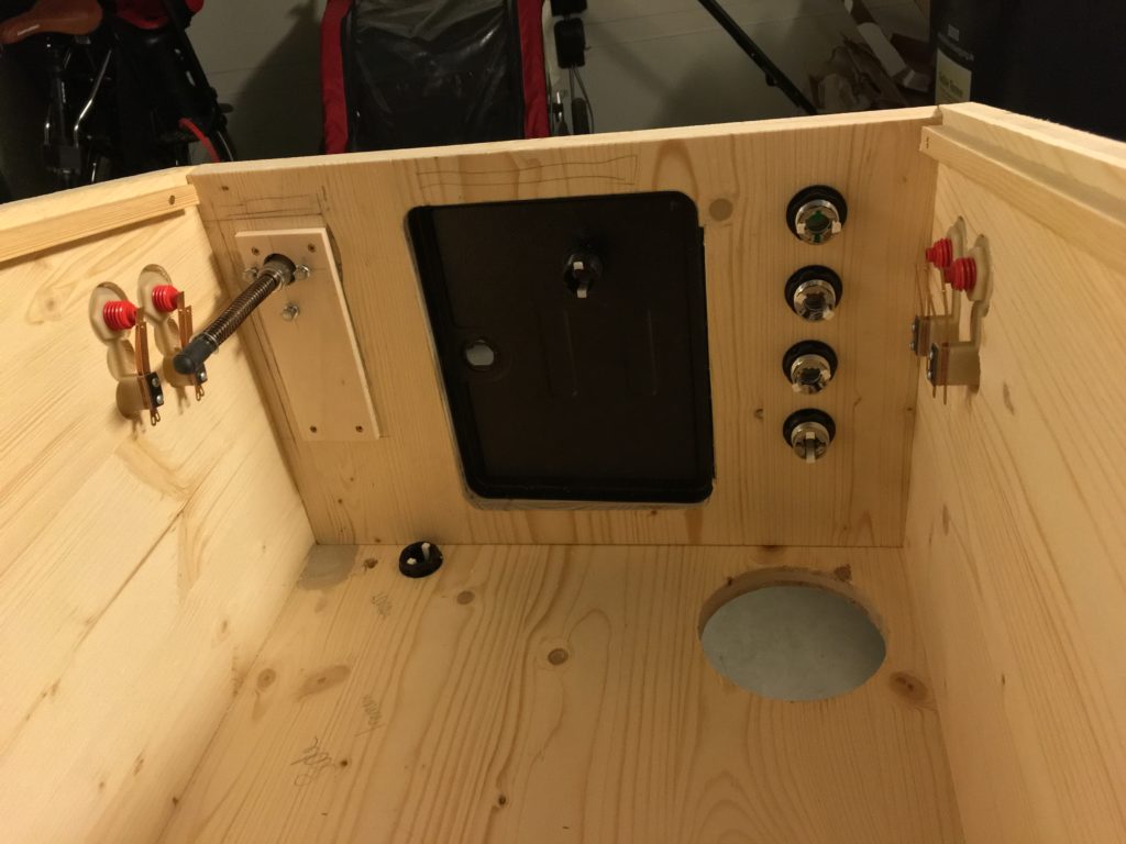
Test assembly of my arcade buttons, coin door with button and analog plunger as well as red leafswitch flipper buttons (Flipper + MagnaSave)
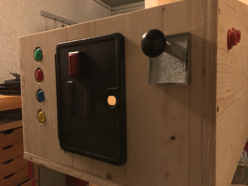
Arrangement of the buttons in the cabinet with service door fitted. Below the service door you can see the on/off button for the computer. On the right, the circular cut for the 120mm intake fan (outtake in the back of the cabinet).
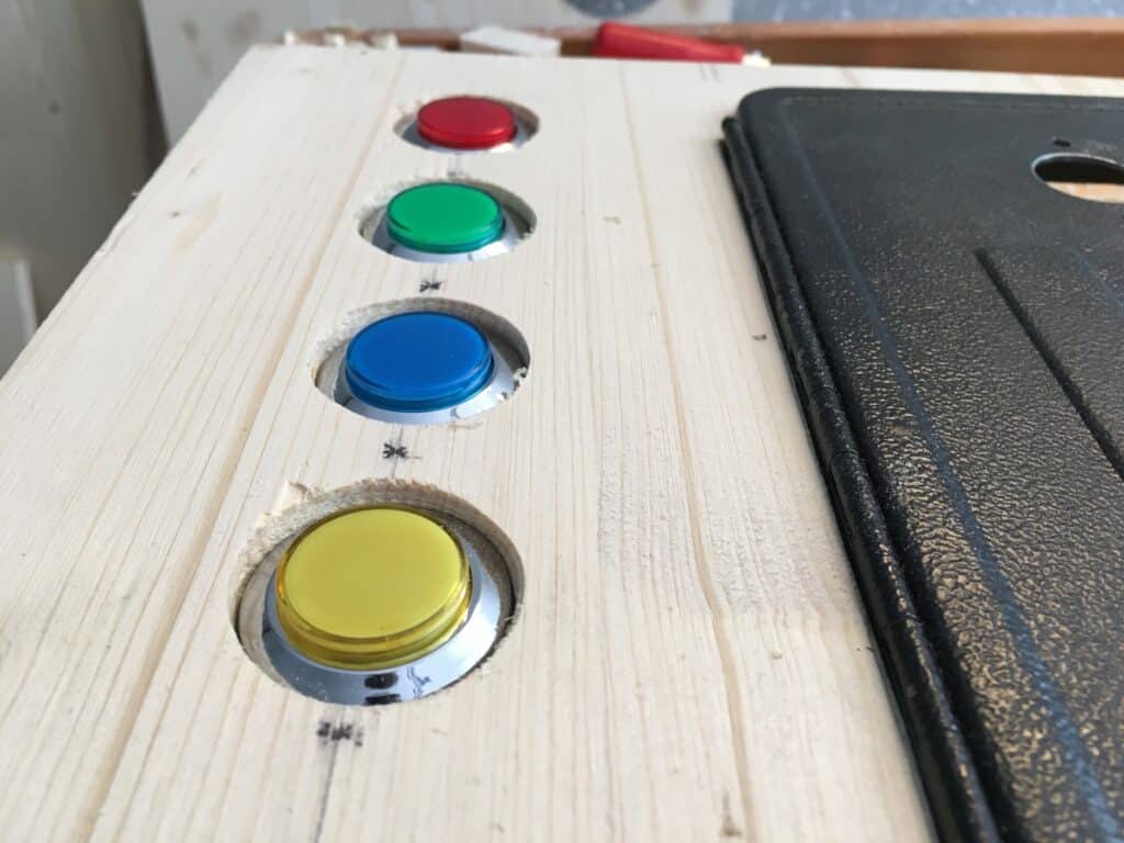
Testfitting of the four sunk, illuminated LED operating buttons of the virtual pinball: Start, Enter, Reload Table, Exit Table.
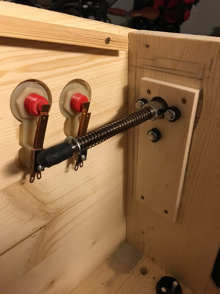
Mounted Virtual Pinball Leaf Switch Flipper Buttons. Due to the short thread length of the buttons, I used a 60mm Forster drill approx. 10mm deep to have enough play for the plastic nuts. Next to it is the test-mounted analog pinball plunger. More about assembling & connecting the analog plunger in Part 5: Install an analog plunger in Virtual Pinball (German only, so far).
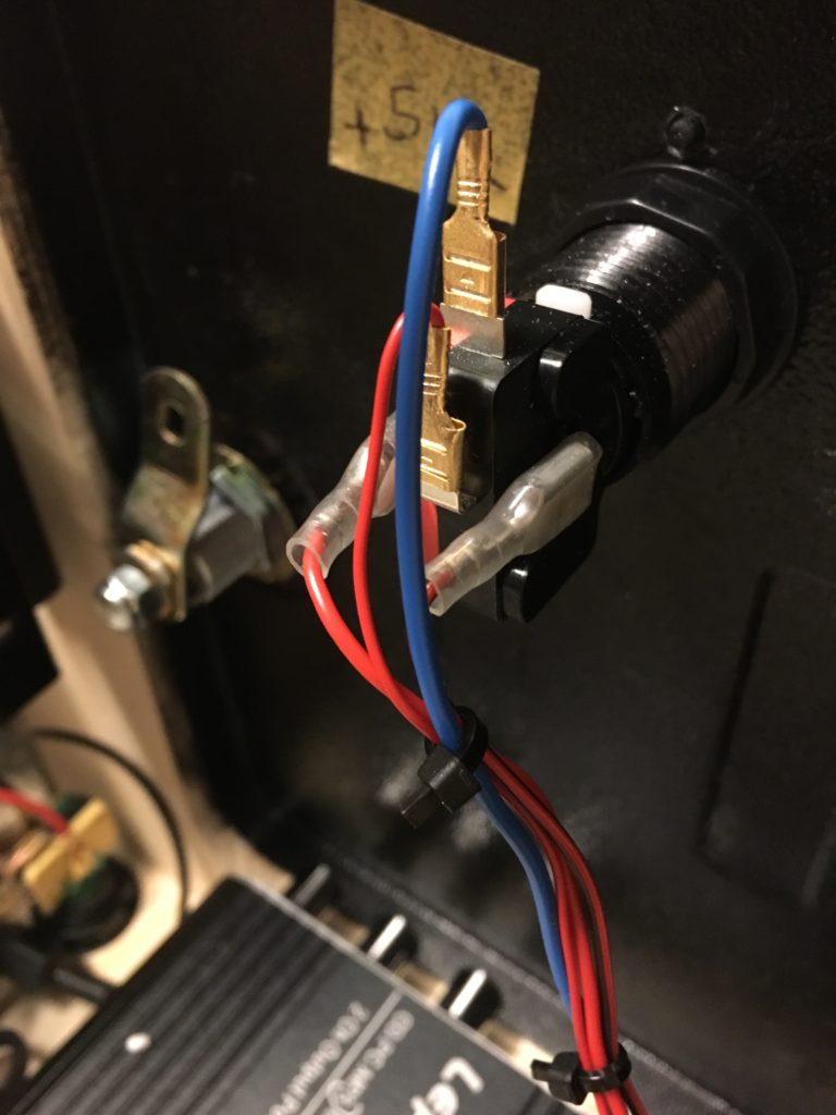
5V LED Coin button, mounted in the service door of the Virtual Pinball. Microswitch is wired to my PinIn1 controller board.
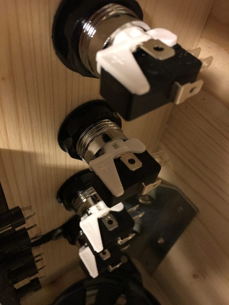
The microswitch arcade buttons with 12 V LEDs. 4 ports each: 2x switch, 2x LED.
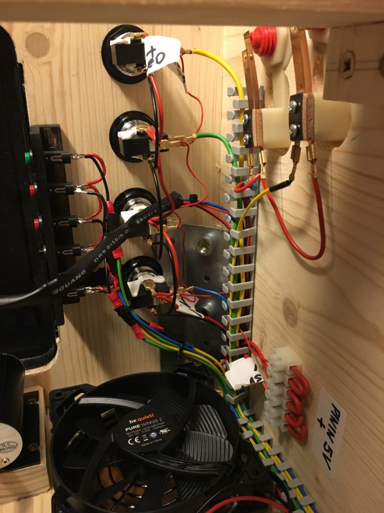
Wiring of the pinball buttons: Center the 4 LED arcade buttons (12V), left 5 service buttons easy accessible through the service door, right the Leaf Switch pinball buttons with the distinctive copper contacts for real pinball feeling.
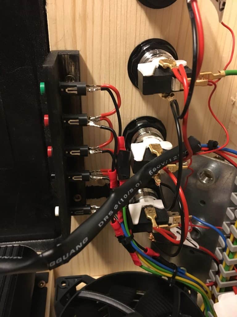
Next photo: The service buttons (white, black, 2x red and green) within the service door e.g. for controlling the volume.
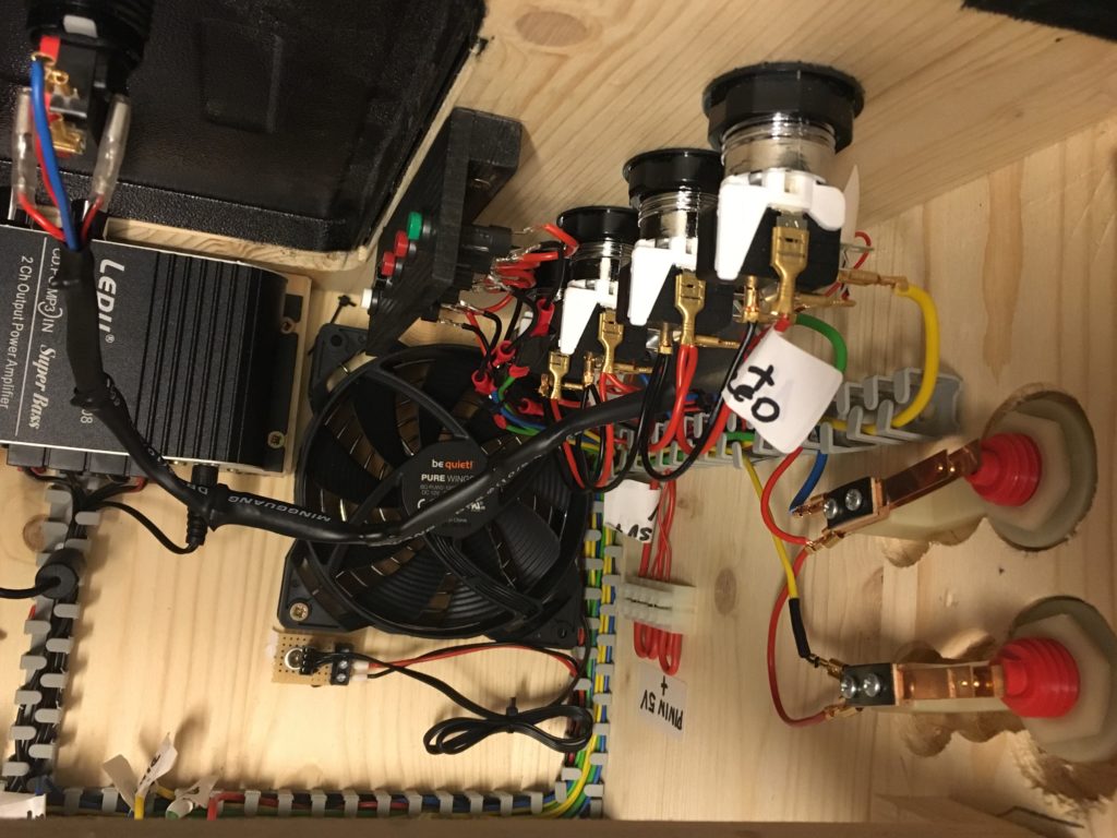
The ready-wired pinball buttons from above, including the fan and audio amplifier (left) for the speakers in the backbox. Amp accessible via the service door
I put together some helpful information and pictures about VPIN cable management in Part 7: cable management in my virtual pinball (in german only, so far.).
Next Part:
Part 5: How to install an analog plunger in a virtual pinball machine…
Comments (1)
How to build a Virtual Pinball Cabinet (VPIN) - virtual-pinball-cabinet.comsays:
29/04/2019 at 19:30[…] pinballs had like “real” clacking of pinball fingers, solenoids, bumpers and toys, real pinball buttons to play, a working manual ball trigger (analogue plunger), even the steel ball moves, when you push the […]